SECTION 6.5
509
Scan Conversion Details
Note:
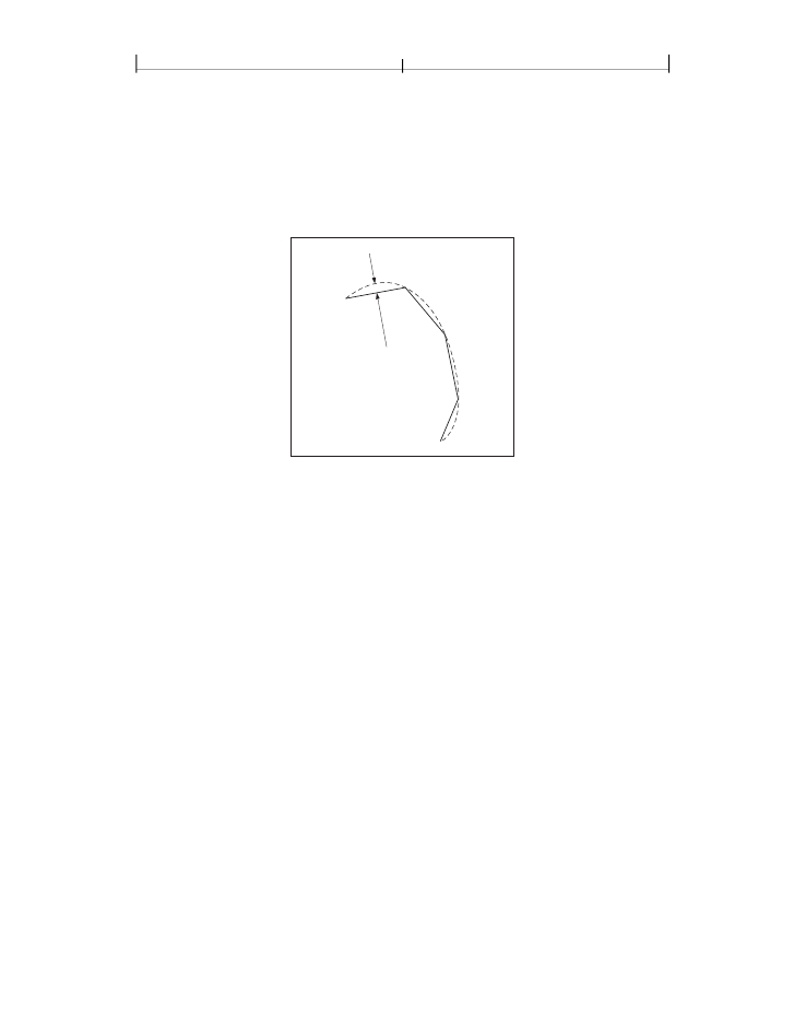
Although the figure exaggerates the difference between the curved and flat-
tened paths for the sake of clarity, the purpose of the flatness tolerance is to control
the precision of curve rendering, not to draw inscribed polygons. If the parameter’s
value is large enough to cause visible straight line segments to appear, the result is
unpredictable.
Flatness error
tolerance
FIGURE 6.6
Flatness tolerance
6.5.2 Smoothness Tolerance
The
smoothness tolerance (PDF 1.3)
controls the quality of smooth shading
(type 2 patterns and the
sh
operator) and thus indirectly controls the rendering
performance. Smoothness is the allowable color error between a shading approx-
imated by piecewise linear interpolation and the true value of a (possibly non-
linear) shading function. The error is measured for each color component, and
the maximum error is used. The allowable error (or tolerance) is expressed as a
fraction of the range of the color component, from 0.0 to 1.0. Thus, a smoothness
tolerance of 0.1 represents a tolerance of 10 percent in each color component.
Smoothness can be specified as the value of the
SM
entry in a graphics state
parameter dictionary (see Table 4.8 on page 220).
Each output device may have internal limits on the maximum and minimum
tolerances attainable. For example, setting smoothness to 1.0 may result in an in-
ternal smoothness of 0.5 on a high-quality color device, while setting it to 0.0 on
the same device may result in an internal smoothness of 0.01 if an error of that
magnitude is imperceptible on the device.